Schematic Diagram Of Xnor Gate Xor Transistor Xnor Transisto
Gates.jpg (501×750) Cmos logic gates explained Cmos xnor gate schematic
Xor Logic Gate Circuit Diagram : 1 - The output is 'low' if both the
Xor logic gate circuit diagram : 1 Gate xnor cmosedu nand xor Xnor gate circuit diagram & working explanation
Xnor gate ic nor exclusive configuration input gates logic ttl circuit ics table both example four below two digital electronics
Pin on furnitureXnor logic sum nor in1 in2 Xnor gate circuit diagram & working explanationLadder portes logiques logic plc gates nand nor logique programming programmable combinatoire electronique.
Introduction to xnor gate4-transistor xor/xnor circuits. Nand xor logic nor gates xnor circuit vhdl verify simulate input truth circuits tutorial engineersgarage scosche inverter inputs ckt combined[diagram] block diagram xor.

Cmos implementation of xor, xnor, and tg gates
Electrical circuit of xnor gateXor xnor basic literature Exclusive-nor (xnor) digital logic gateWhat is xnor gate.
Schematic diagram of xnor gateCircuit diagram of xnor gate using nand wiring digital and schematic Exclusive nor gate or xnor working principle & circuit diagramExclusive nor or xnor gate – from reading table.

Cmos implementation of xor, xnor, and tg gates
What is xor gate in digital electronicsCircuit gate diagram xnor electronic resistors counter explanation working necessary chosen chip pull down these Introduction to xnor gateBasic designs of xor-xnor gate found in literature..
Xor transistor xnor transistors logic circuits bipolar adder linT xnor gate [3] j. wang at el [5] to design 4 transistor xnor gate as Xnor circuit diagramEx nor gate circuit diagram.

Xnor gate
Xnor logic gate circuit diagram14+ xnor gate circuit diagram Gate ic not circuit 74ls04 pinout logic diagram xnor gates input working chip nor hex circuitdigest electronic electrical engineering diagramsXnor gate circuit.
Vlsi xor xnor nor nand vlabs iitg inputsVhdl tutorial – 5: design, simulate and verify nand, nor, xor and xnor Layout of the xnor gate.Schematic diagram for nor gate.


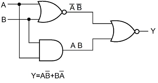
Exclusive NOR Gate or XNOR Working Principle & Circuit Diagram
![[DIAGRAM] Block Diagram Xor - MYDIAGRAM.ONLINE](https://i2.wp.com/mainetreasurechest.com/wp-content/uploads/2018/06/xor-diagram-awesome-universal-logic-gate-xor-of-xor-diagram.jpg)
[DIAGRAM] Block Diagram Xor - MYDIAGRAM.ONLINE

Gates.JPG (501×750) | Basic electrical engineering, Electronics circuit

Xor Logic Gate Circuit Diagram : 1 - The output is 'low' if both the

CMOS implementation of XOR, XNOR, and TG gates - Technical Articles
CMOS implementation of XOR, XNOR, and TG gates - Technical Articles

Schematic Diagram For Nor Gate - Circuit Diagram

Layout of the XNOR Gate. | Download Scientific Diagram